RON HAZELTON:
You know, it used to be that I never gave a lot of thought to lighting but I feel differently about that now, especially here in this room, the kitchen because this is a social gathering spot and a workplace.
That means we need one kind of lighting for ambience and a different kind to work by. And there's been one spot in this kitchen where I've never really been happy with the light, and that's right up here underneath these cupboards.
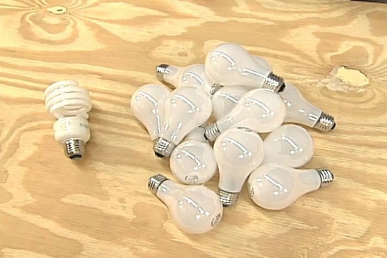
So today, I'm going to install some undercabinet lighting of a brand new type. Now this is the lighting fixture that I'm going to use today. It's an LED light and it has several advantages. For one, it's five times more energy efficient than an incandescent light and it has an incredibly long life, 60,000 hours.
Now to give you an idea of just how long that is, if you were to burn this 10 hours a day, 365 days a year, it would last more than 15 years. They're very attractive, low profile, in fact in my case, they're gonna be virtually invisible.
And because they're low voltage, they're very simple to install. Now I've just kind of laid everything out here to see were they going to fit up underneath the cabinets and they're going to be powered by this transformer. That will step the household current down to the 12 volts AC.
I think what I'm gonna do is probably mount this transformer up here in the cabinet like that and then the power for that is going to come from a switch that I'm gonna put right in here. Now this is an old telephone junction box.
I don't use that anymore, so I'm gonna take advantage of that location and install the switch there. Oh, and by the way, these are dimmable. Step one is to remove the existing telephone jack by first taking off the cover plate, then removing the screws that hold the jack itself in place.
Now I can just pull the assembly from the box and clip off the wires. Finally, I take out the box itself. Okay, here's the challenge that confronts me. I've got a thread an electrical wire from the basement up to this opening in the wall right here.
I'm gonna do that by drilling a hole in the bottom of this wall, actually on the inside of the bottom of this wall down in the basement. The question is, where do I drill that hole so that it will line up pretty much exactly with this opening?
Well, here's how I'm gonna do it. First of all, I'm gonna measure from the center of that opening to the edge of this casing right here. That's about 26 and a half inches. Then I'll come down here and measure over the same amount -- 26 and a half and make a mark.
Next, I remove the shoe molding at the bottom of the baseboard. Then, using a long shaft quarter inch drill bit, I begin boring a hole through the floor at an angle. I exit at a point in the basement that's directly below the center of the wall cavity.
Before removing the bit, I mark the exit location, then go back upstairs and back out the drill. Now, using what's called a bell hangers bit, I bore a larger three-quarter inch hole up into the hollow part of the wall. Next, I insert the end of a stiff wire, called a fish tape into the hole I've just drilled and push it up inside the wall.
Now if I've drilled at the right place, the tape should end up very close to the box opening. I continue pulling the fish tape through until just a short length is left in the basement. To the end, I attach an electrical cable, and wrap tape tightly around the connection, then I head back upstairs and being pulling on the fish tape once again, drawing the attached cable from the basement up into the kitchen.
I cut the tape and cable apart, then go back back downstairs to connect into an existing power supply. I uncoil a few more feet of wire and snip it off. Then I use a right angle drill and auger bit to bore a series of holes through the floor joists, so that I can run the cable perpendicular to them, and at the same time, keep it high up and out of reach.
This junction box houses an electrical line that supplies power to my garbage disposal. I'll borrrow a bit of electricity from here. My voltage tester confirms it's an active circuit. After flipping off the breaker, I test again to make sure the line is deactivated.
Next, I slip the plastic sheathing on the cable, strip off the wire insulation, install a connector in the existing junction box, snug up the lock nut, pass the wires through and tighten the connector clamp that secures the cable to the box.
To connect into this circuit, all I need to do is twist together, wires of the same color. Black to black, white to white, green to green then screw on the wire nuts. All that's left to do down here is replace the box cover and drive in a few cable staples.
Now let me give you a little road map as to where we are and where we're going. Now this is the power line that I brought up from the basement, right here, and eventually, there will be a switch in this spot and then up here is the transformer.
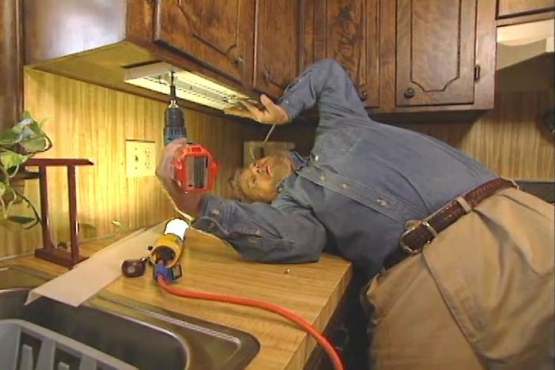
Now this, remember, is going to reduce the line voltage, 120 volts down to 12 volts for the lights. What I need to do now is to run a wire from up here in the cupboard down to this opening in the wall. I begin by using the bell hanger bit again to drill through the cabinet back and into the wall cavity.
Now, I can pass the fish tape into the hole --locate it with my other hand and pull it through the switch box opening. Once again, I attach the cable, wrap it snugly with electrical tape and pull the wire into the switch box opening through the wall and into the cabinet above.
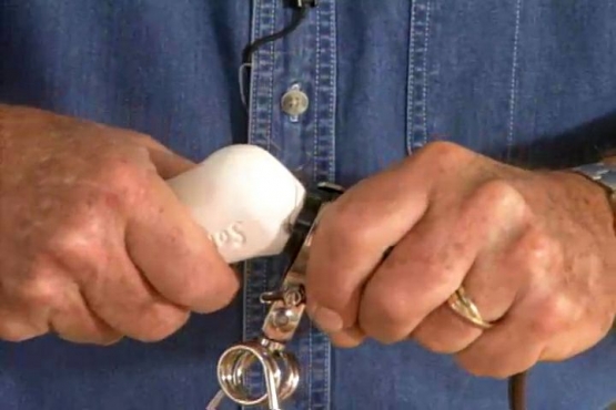
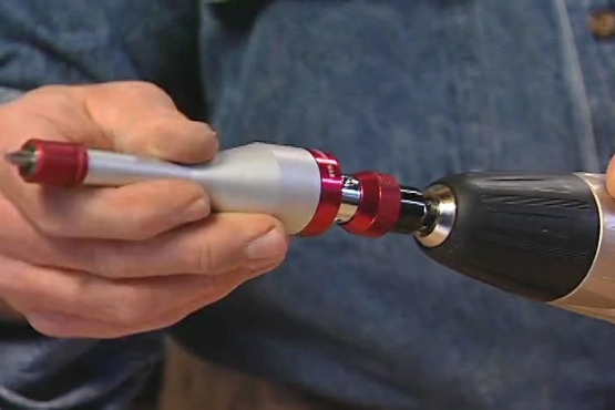
For this run, I'm using BX armored cable. This tool, a cable armor stripper, uses a rotating wheel to cut through the outer metal jacket. The armor is then pulled off, leaving the wires inside undamaged. Now, I can slip the wires into an electrical box and tighten the connector that clamps the armored outer cable in place.
The cable from the basement is pushed into the bottom of the box and held in place with a similar but slightly different connector. Now unlike electrical boxes used in new construction, this box does not have to be attached to the framing.
Instead, it's held in place by wings that expand outward as screws on the front are tightened. In effect, the box is clamped, front and back to the wall material, in this case, wallboard.
To install the switch, I first strip a bit of insulation off the wire ends. Then twist the white or neutral wires together and secure them with a wire nut. This switch has two black pigtails. One I connect to the black wire coming from the basement. The other I attach to the black wire going to the transformer.
Finally, I connect the green ground wires together. Now I set the switch into the box, secure it in place with mounting screws, place the cover plate in position and install the screws.
I'm going to start by removing this knockout from the transformer and putting in a connector designed just for armored cable. Now, I can slip the wires into place, tighten the set screw and set the transformer in position.
Again, I connect the light colored wires to each other, green to green, black to black, and white to white. To run the low voltage wires to the first row of lights, I'm boring quarter inch holes through the cabinet shelves so I can feed the wire from the transformer to the underside of the cabinet. These small plastic cable holders offer a simple and effective way to secure the wires while avoiding the risk of damage.
[SOUNDS OF BANGING]
The light fixtures themselves will be held in place with these brackets that simply screw to the underside of the cabinets. Once everything's in place, the lights just snap into the brackets.
This is a modular lighting system. Low voltage wire plugs into the end of the fixture. Short pigtails like this; quickly connect one unit to the next. To run the wire to the adjacent cabinets, I'm going up -- and across.
When I get to the other side of the window, I bore a small hole through the top of the cabinet, near the rear corner -- and a hole through each shelf. Then it's simply a matter of threading the wire from the top down to the underside, once again.
Here, I put up more brackets -- snap in the light fixtures -- and plug in the wires. And remember, this is all low voltage wiring. To conceal the wire running across the molding above the kitchen window, I'm using this plastic raceway.
Peeling off the protective backing exposes a pressure sensitive adhesive on the bottom. Once it's pressed in place, it will blend with its surroundings and completely conceal the wire that is just pushed through a slot in the side.
I have just one small bit of wiring left to do. The low voltage wires carrying power to the light fixtures need to be connected to the low voltage output from the transformer. It's this reduction in current from the potentially dangerous 120 volts to only 12 that makes this system so safe and easy to work with.
You know, LED lighting is the wave of the future but the good news is, you can have it in your own home right now. And I can't think of any better application for it than here in the kitchen. But you know what? I've been talking for a long time. Why don't you take a look for yourself.